

Compressed Air Pipe and Fittings: The Definitive Guide to Designing and Specifying a High-Performance Industrial Air System
Compressed air is the invisible workhorse of Australian industry. In manufacturing plants, automotive workshops, food processing facilities, mining operations, and construction sites across the country, compressed air powers pneumatic tools, actuates valves and cylinders, conveys materials, controls processes, and performs dozens of other critical functions. Yet despite how fundamental it is to operations, the distribution infrastructure that delivers compressed air around a facility — the pipe, fittings, valves, and connections — is routinely under-engineered, poorly specified, and inadequately maintained.
The consequences are measurable and significant. Compressed air leaks — which in a poorly designed or ageing system can account for 20 to 40 per cent of total air generated — represent direct energy waste at a time when Australian industrial electricity costs are among the highest in the developed world. Pressure drop through undersized or poorly configured piping forces compressors to work harder, increasing wear and energy consumption. Contamination from corroding pipe degrades air quality and damages downstream equipment. And a distribution system that can't be easily modified becomes a constraint on operational flexibility as facilities evolve.
Getting compressed air pipe and fittings right is not a minor detail — it's a fundamental engineering decision that affects facility operating costs, production reliability, and air quality for the life of the installation. This guide provides the technical framework that engineers, project managers, and factory managers need to design, specify, and procure a compressed air distribution system that performs.
The True Cost of a Poor Compressed Air Distribution System
Before diving into specification details, it's worth establishing why the quality of compressed air piping infrastructure matters so much financially — because in our experience, this is where many facilities are losing money they don't realise they're losing.
The Energy Cost of Leaks
A single 3mm leak in a compressed air system operating at 700 kPa can waste approximately 20 litres of air per second — around 72 cubic metres per hour. At typical Australian industrial compressor efficiencies and electricity tariffs, that represents roughly $3,000 to $5,000 in wasted electricity per year from a single leak. Most industrial facilities have multiple leaks. The Compressed Air Challenge (a US Department of Energy initiative whose research is widely referenced in Australian industrial efficiency programmes) estimates that the average industrial compressed air system loses 25 to 30 per cent of generated air to leaks.
The majority of those leaks occur at joints and fittings. A distribution system designed with high-integrity fitting connections — rather than threaded joints or poorly maintained push-fit connections — is simply a more energy-efficient system from day one.
The Productivity Cost of Pressure Drop
Every metre of pipe, every elbow, every tee, and every valve in a compressed air distribution system creates pressure drop. When the cumulative pressure drop between the compressor outlet and the most remote point of use is excessive, the delivered pressure at the tool or equipment is insufficient for effective operation — forcing operators to raise compressor outlet pressure to compensate, which increases energy consumption, or to accept degraded tool performance, which affects production quality and output.
Correctly sized pipe, a well-designed loop layout, and appropriately specified fittings with low flow resistance minimise pressure drop and allow the system to operate at the lowest compressor outlet pressure consistent with the application's requirements — which is always the most energy-efficient operating point.
The Quality Cost of Contamination
Internal pipe corrosion introduces rust particles, scale, and moisture into the compressed air stream. For applications where air quality matters — spray painting, food and beverage production, pharmaceutical manufacturing, electronics assembly, precision pneumatics — contaminated air directly affects product quality, equipment reliability, and in regulated industries, compliance. The cost of additional filtration, equipment damage, product defects, and regulatory non-compliance attributable to poor air quality from corroding pipe infrastructure can far exceed the cost of specifying corrosion-resistant piping in the first place.
Piping Materials: Choosing the Right Option for Your Application
The single most impactful specification decision in compressed air piping design is material selection. The material determines corrosion resistance, installation method, modification flexibility, air quality implications, and total cost of ownership over the life of the system.
Aluminium Compressed Air Pipe
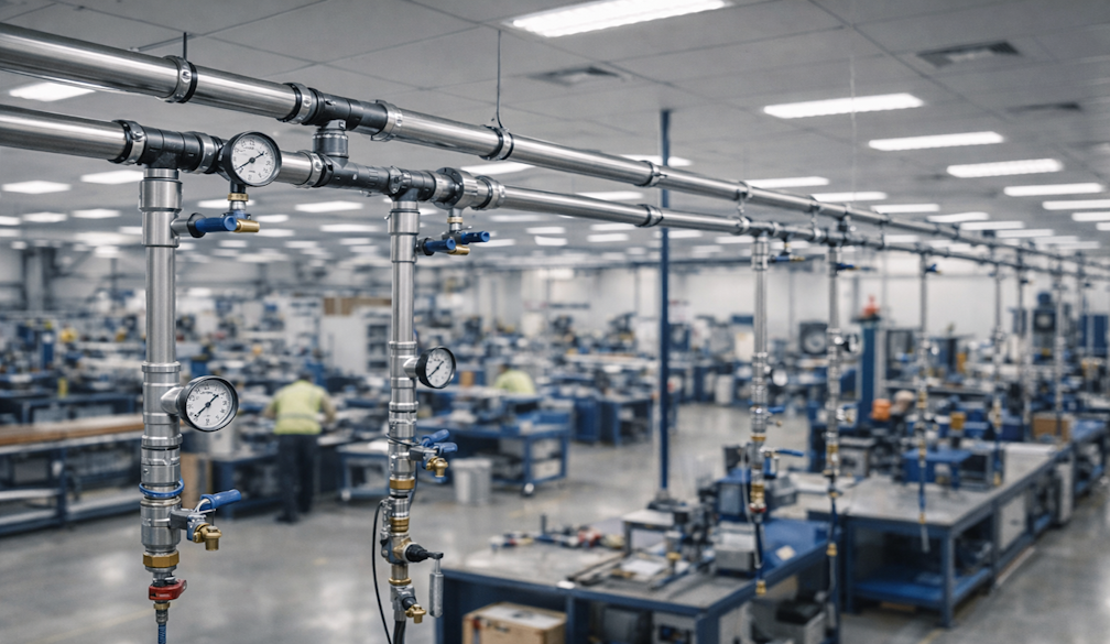
Aluminium compressed air piping systems have become the dominant specification for new industrial compressed air installations in Australia and globally over the past two decades, largely displacing galvanised steel as the professional standard. The reasons are compelling: aluminium doesn't corrode internally under normal compressed air service conditions, delivers clean air without the rust contamination associated with steel, installs significantly faster than threaded steel pipe, and produces a neat, professional-looking installation.
Modern aluminium compressed air pipe systems use push-fit or mechanical fittings that require no threading, welding, or solvent cement — connections can be made quickly with basic tools, and the system can be extended or modified with minimal disruption. The smooth internal bore of aluminium pipe also minimises friction losses and contributes to lower pressure drop compared to older steel installations.
Aluminium is well-suited to a broad range of industrial compressed air applications and working pressures. It handles elevated temperatures better than polyethylene alternatives and is available in a comprehensive range of pipe diameters and fitting configurations. For most new compressed air installations in manufacturing, automotive, food processing, and general industrial environments, aluminium pipe is the specification of choice.
Polyethylene (Poly) Compressed Air Pipe
Engineered polyethylene compressed air pipe — specifically rated for compressed air service, distinct from standard plumbing poly — offers some specific advantages that make it attractive in certain applications. Poly is generally lower cost than aluminium in both materials and fittings, making it an economical option for large-scale distribution networks. It is lightweight and flexible, simplifying installation in complex routing situations, and its chemical resistance is excellent for environments involving exposure to aggressive substances.
The critical caveat — which cannot be overstated — is that only polyethylene pipe specifically rated and manufactured for compressed air service should ever be used in a compressed air system. Standard plumbing poly pipe is absolutely not suitable for compressed air and must never be substituted. Compressed air stores far more energy than water at equivalent pressures, and the failure of an incorrectly specified poly pipe under compressed air can be catastrophic.
Within its rated parameters, quality compressed air poly pipe performs reliably and delivers the same leak-minimisation and corrosion resistance benefits as aluminium. The choice between poly and aluminium typically comes down to application pressure and temperature requirements, the scale of the installation, and specific environmental factors.
Stainless Steel Pipe
For applications involving particularly aggressive environments — high humidity, chemical exposure, marine or coastal installations, or hygienic applications in food and pharmaceutical facilities — stainless steel pipe offers corrosion resistance that aluminium and poly cannot match. Grade 316 stainless steel is the typical specification for corrosive compressed air service.
Stainless steel compressed air pipe is more expensive than aluminium and requires more skilled installation, but where the operating environment warrants it, the lifecycle performance and reduced maintenance requirement justify the additional upfront investment. It is also the appropriate specification for high-purity compressed air applications where contamination from any source is unacceptable.
What to Avoid: Galvanised Steel and PVC
Two piping materials that should not be specified for new compressed air installations deserve specific mention.
Galvanised steel pipe — while still found in older facilities and sometimes still offered as a low-cost option — corrodes internally over time, shedding rust and scale into the air stream and developing leaks at corroded joints and pipe sections. The installation is labour-intensive, modification is difficult and disruptive, and the long-term maintenance cost consistently exceeds that of modern alternatives. There is no good reason to specify galvanised steel for a new compressed air installation today.
PVC pipe is dangerous in compressed air service and must never be used. Unlike water, compressed air is compressible — it stores energy. When PVC pipe fails under pressure, it shatters rather than splitting cleanly, producing high-velocity plastic shrapnel that can cause serious injury. PVC is not rated for compressed air service, and its use in compressed air systems is widely prohibited under Australian workplace health and safety legislation.
Fitting Selection: Where Leaks Actually Happen
In any compressed air distribution system, fittings are the primary source of leaks. The number of joints in a system, the type of connection used, and the quality of installation all directly determine the leak rate — and therefore the energy efficiency — of the system from the day it is commissioned.
Push-Fit Fittings
Push-fit fittings — where the pipe is simply pushed into the fitting body to create a sealed connection — are the dominant technology in modern aluminium and poly compressed air pipe systems. Quality push-fit fittings use internal O-rings and grab rings that create a reliable, low-leak connection without the need for sealants, tapes, or threading. They can be assembled quickly, require no specialist tools for basic connections, and allow the pipe to be released and repositioned if the installation needs adjustment during commissioning.
It is important to use fittings specifically designed for the pipe system being installed. Mixing fittings from different manufacturers, or using fittings not rated for the operating pressure and temperature of the application, is a common source of system failures. Always verify that the complete system — pipe and fittings together — carries a pressure rating appropriate for the application.
Compression Fittings
Compression fittings use a ferrule that is mechanically compressed onto the pipe as the fitting nut is tightened, creating a seal between the pipe and fitting body. They are widely used in instrumentation and small-bore compressed air applications, and can be used with a range of pipe materials. Compression fittings generally require more careful installation technique than push-fit to achieve reliable seal integrity, but are well-proven in demanding service conditions.
Threaded Fittings
Threaded fittings — using BSP or NPT parallel or tapered threads with appropriate sealant — remain common for connecting compressed air pipe systems to compressors, receivers, valves, regulators, and equipment drops. Thread quality, correct sealant selection, and proper thread engagement are all critical to achieving a reliable seal. Threaded connections should be minimised in the distribution pipework itself where push-fit or compression alternatives are available, reserving them for the equipment connection points where they are most appropriate.
System Design Principles That Drive Performance
Beyond material and fitting selection, the layout and design of the compressed air distribution system fundamentally determines its performance. These are the design principles that separate a well-engineered system from one that creates ongoing operational problems.
Ring Main vs. Dead-End Distribution
A ring main (or loop) layout — where the compressed air distribution pipe forms a closed loop around the facility with the compressor feeding into the loop — delivers air to any draw-off point from two directions simultaneously. This halves the effective pipe length to any point of use, significantly reducing pressure drop and improving flow balance across the system. It also provides inherent redundancy: if a section of the ring requires isolation for maintenance, air can continue to be supplied to most of the facility from the other direction.
Dead-end or branch layouts — where pipes run from the main to specific areas without looping back — are simpler to install but result in higher pressure drop at remote points of use, uneven pressure across the facility, and no redundancy in the event of a fault or maintenance requirement. For any facility with more than a handful of air connection points, a ring main design is strongly recommended.
Pipe Sizing and Velocity
Compressed air pipe should be sized to keep air velocity within the distribution mains below approximately 6 to 9 metres per second at peak demand flow. Higher velocities result in increased pressure drop and can cause moisture entrainment and noise. Drop pipes — the vertical connections from the main to equipment — should typically be sized to limit velocity to 15 metres per second or less.
Pipe sizing calculations should account for:
- Peak simultaneous demand — not just connected equipment total, but the realistically expected simultaneous operating load
- Total equivalent pipe length — including fittings, which contribute resistance equivalent to additional pipe length
- Maximum acceptable pressure drop — typically 0.1 to 0.3 bar across the distribution system from compressor outlet to most remote point of use
- Future expansion allowance — oversizing main distribution runs by one pipe size to accommodate anticipated future growth is almost always a worthwhile investment
Drainage and Moisture Management
Moisture in compressed air is unavoidable — the compression process concentrates water vapour, and some of that moisture will condense in the distribution pipework. Unmanaged moisture causes corrosion in steel systems, contaminates the air stream, and can cause operational problems in pneumatic equipment and controls.
Good drainage design includes: slight falls in horizontal pipe runs (towards drain points, not away from them), drain legs at low points and before important equipment connections, automatic condensate drains at regular intervals in longer horizontal runs, and after-coolers and refrigerant dryers on the compressor outlet where air quality requirements warrant it. Moisture management is a system design discipline, not an afterthought.
Isolation, Regulation, and Zoning
A well-designed compressed air distribution system is divided into logical zones, each with isolation valves that allow sections of the system to be isolated for maintenance or modification without shutting down the entire facility. Pressure regulators at point-of-use connections allow equipment to operate at its optimal pressure without requiring the entire system to operate at the highest required pressure — which reduces energy consumption across the board.
Lockable isolation valves on all major branches, clear labelling of isolation points, and a system schematic that accurately reflects the as-installed configuration are all elements of a professionally designed compressed air system that pays dividends during maintenance, fault-finding, and future modifications.
Commissioning, Testing, and Documentation
A new or upgraded compressed air piping system should be pressure tested before commissioning — typically to 1.5 times the maximum working pressure, held for a defined period, and inspected for any pressure decay indicating a leak. Any leaks identified during pressure testing should be rectified before the system is put into service.
Commissioning documentation — including an as-installed system schematic, pressure test records, material certificates for pressure-rated components, and any relevant compliance documentation — should be prepared at installation and retained for the life of the system. This documentation is essential for maintenance planning, future modifications, and demonstrating compliance with AS/NZS 3788 (Pressure Equipment — In-Service Inspection) and relevant workplace health and safety requirements.
Ongoing Maintenance: Protecting the Investment
Even the best-designed and best-installed compressed air piping system requires ongoing maintenance to sustain its performance. A structured maintenance programme should include:
- Regular leak detection surveys — ultrasonic detection is the most effective method for identifying small leaks that are inaudible; quarterly surveys are recommended for active manufacturing environments
- Prompt repair of any leaks identified — leaks should be logged, prioritised, and repaired within a defined timeframe, not added to an ever-growing list
- Periodic inspection of fitting connections, particularly in areas subject to vibration or thermal cycling
- Annual review of system pressure settings — ensure compressor outlet pressure is set to the minimum consistent with application requirements
- Condensate drain maintenance — automatic drains should be tested regularly to confirm they are operating correctly
Facilities that implement structured compressed air maintenance programmes consistently achieve lower leak rates, lower specific energy consumption (energy per unit of air delivered), and longer equipment service life than those that manage maintenance reactively.
Making the Right Specification Decision
For engineers and project managers specifying a new compressed air distribution system — or reviewing an existing one — the decision framework is clear. Start with the application requirements: operating pressure, flow demand, air quality needs, and environmental conditions. Select piping material that matches those requirements and delivers the best lifecycle value. Design the system layout for minimum pressure drop, proper moisture management, and operational flexibility. Specify fittings that minimise leak potential. And commission, test, and document the installation properly.
A well-designed compressed air piping system is not a cost centre — it's an operational asset that pays for itself through lower energy consumption, reduced maintenance costs, better air quality, and higher production reliability. The investment in getting the specification right is always returned many times over across the life of the installation.
For factory managers and business owners reviewing ageing compressed air infrastructure, the calculus is similar: the ongoing cost of operating a leaking, corroding, pressure-dropping steel system almost always exceeds the cost of replacing it with a modern, correctly specified alternative. Energy savings alone frequently deliver payback within two to three years. The operational and quality benefits continue for the life of the new system.


